

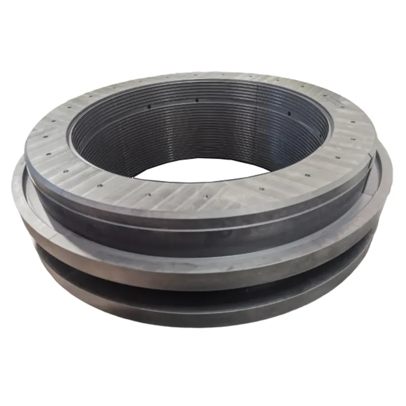
PEEK Balance Components Engineering Guidelines
Advanced Polymer Thrust Balancing Solutions for Centrifugal Pumps
1. Core Design & Calculation Data
Axial Thrust Balancing Formula
- $F_{balance}$ = Hydraulic balancing force
- $\Delta p$ = Pressure differential across the balancing structure
- $A_{eff}$ = Effective pressure-bearing area (must be determined based on actual flow fields and leakage paths; do not blindly use simple annular projected area).
Clearance Design Principles
Warning: Absolutely do not directly apply metallic component clearance standards. PEEK and metals differ completely in elastic modulus, thermal expansion coefficient, creep, and wear characteristics. Clearances must undergo rigorous engineering re-evaluation.
2. PEEK Material Performance Indicators
Pure PEEK Base Data
(Based on VICTREX PEEK 450G, 23°C lab data)
- Flexural Strength (ISO 178): 165 MPa
- Compressive Stress (ISO 604): 125 MPa
- Charpy Impact (ISO 179/1eA): 7 kJ/m²
- Melting Point (ISO 11357-3): 343°C
Warning: This is NOT the allowable working or dry friction temperature. Localized thermal damage occurs well below the melting point.
Carbon Fiber (CF) Reinforced PEEK
- Higher stiffness and superior creep resistance.
- Improved thermal conductivity and dimensional stability.
- Note: Not universally suitable for abrasive slurries; proper tribological system verification is mandatory.
Hardness Reporting Standards
- Applicable Scales: Shore D (ISO 868 / ASTM D2240) or Rockwell M/R (ISO 2039-2 / ASTM D785).
- Prohibited: Strict ban on using the Rockwell C (HRC) scale to describe PEEK hardness.
3. Operating Environments & Media Limitations
Chemical Bans
Strictly prohibited for use in concentrated sulfuric acid or other strong oxidizing acid environments. High concentration sodium hydroxide (high pH) must also undergo specific testing and cannot be blindly applied under the assumption of “general corrosion resistance”.
Particles & Slurry
Evaluating particle hardness must utilize Mohs, Vickers, or Knoop scales, NOT Shore D. The assumption that “particle size is less than 1/3 of the clearance” is insufficient for safe operation and will still induce 3-body abrasive wear.
Prohibited Conditions
Uncontrolled dry running (lack of water/lubrication), operating beyond tested temperature/pressure/vibration limits, and utilizing unverified shaft-end gas seals in compressors are strictly forbidden.
4. Recommended Applications
Applicable only after thorough verification of residual axial thrust, thermal stability, and wear performance:
Multistage Centrifugal Pumps
Ideal for multistage process pumps, boiler feedwater pumps, and water injection pumps.
Chemical Process Pumps
Suitable for corrosive liquid services, subject to strict media compatibility confirmation (including cleaning agents and fluctuating operating conditions).
Desalination & Injection
Requires strict evaluation of chloride content, suspended/dissolved solids, and cavitation margins before implementation.
5. Common Troubleshooting Guide
Increased Internal Leakage
- Possible Causes:
- Wear, enlarged clearances, damaged mating surfaces, scale accumulation, balance component deformation.
- Recommended Actions:
- Measure radial/axial clearances;
- inspect mating surfaces for scratches or thermal damage;
- check if balance piping is blocked.
Thermal Damage or Smearing
- Possible Causes:
- Dry running, excessive PV load, incorrect clearance design, poor surface finish on mating components.
- Recommended Actions:
- Confirm liquid presence prior to startup;
- check minimum flow/recirculation lines;
- inspect flush/cooling piping.
Excessive Residual Thrust
- Possible Causes:
- Balance area calculation error, blocked balance holes/channels, impeller wear, deviation from design operating conditions.
- Recommended Actions:
- Recalculate pump hydraulics vs. actual differential pressure;
- inspect all throttling channels;
- measure axial displacement and bearing loads.
6. Customization Evaluation Checklist
To ensure a successful PEEK balance disc design, the following parameters must be provided to our engineering team:
- Drawings: Pump cross-sectional drawings, rotor assembly drawings, and current component prints.
- Geometry & Conditions: Shaft diameter, design/operating differential pressures, speed range, start/stop frequency, vibration, and runout limits.
- Fluid Parameters: Composition, concentration, temperature range, viscosity, density, vapor pressure, pH value, and cleaning chemicals used.
- Particle Parameters: Solid phase concentration, particle size distribution, particle hardness (Mohs/Vickers), and filtration schemes.
7. FAQ (Frequently Asked Questions)
Can we use standard metallic clearance design for PEEK components?
No. Absolutely do not directly apply metallic component clearance standards. PEEK and metals differ completely in elastic modulus, thermal expansion coefficient, creep, and wear characteristics. Clearances must undergo a complete engineering analysis specific to the polymer’s behavior.
What hardness scale should be used to specify PEEK?
You must use Shore D (ISO 868 / ASTM D2240) or Rockwell M/R (ISO 2039-2 / ASTM D785). It is strictly prohibited to use the Rockwell C (HRC) scale to describe PEEK material hardness.
Are there any standard certifications for PEEK we should reference?
Standard industrial pump references usually include ISO 5199 or API 610. Warning: ASTM F2026-23 is a specification for surgical implant (medical) grade PEEK. It cannot and should not be used for industrial pump balance disc material qualification.
Is PEEK safe for high-concentration acids or alkalis?
PEEK is strictly prohibited in concentrated sulfuric acid or strong oxidizing acid environments. While generally corrosion-resistant, high concentration sodium hydroxide (high pH) environments must be specifically tested before deployment.
Request a Quote
Submit your engineering parameters below, and our technical team will respond promptly.