

Performance and Technical Parameters
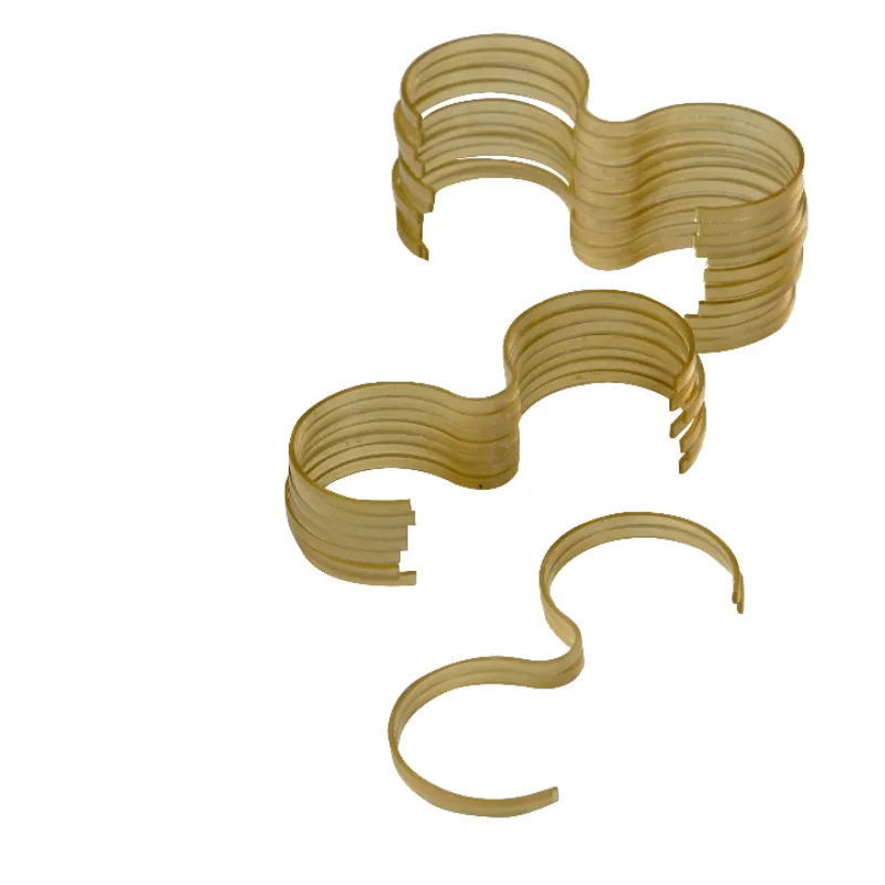
Comprehensive engineering metrics and material properties for precision gear pump seal retainer strips.
| Technical Parameter | Specification Value | Standard / Reference |
|---|---|---|
| Operating Temperature Range | Continuous -40℃ to +260℃, short-term peak +300℃ | ISO 11357 / ASTM D3418 |
| Pressure Capacity | ≤40MPa (high-pressure gear pumps), ≤25MPa (standard type) | ISO 19879 / GB/T 7935 |
| PV Value Limit | Dry friction ≤1.5MPa·m/s, oil lubrication ≤2.8MPa·m/s | ASTM D3702 |
| Friction Coefficient | Oil lubrication 0.05-0.08, boundary lubrication 0.08-0.12, dry friction 0.12-0.18 | ASTM D1894 |
| Wear Rate | ≤3×10⁻⁶mm³/N·m (hydraulic oil), ≤8×10⁻⁶mm³/N·m (water-based) | ASTM G99 |
| Working Clearance | Gear end face clearance 0.03-0.08mm (new), wear limit 0.15-0.25mm | ISO 286 / DIN 71550 |
| Surface Roughness | Working surface Ra≤0.8μm, mounting surface Ra≤1.6μm | ISO 4287 / ASME B46.1 |
| Dimensional Tolerance | Thickness ±0.020mm, length ±0.050mm, width ±0.030mm, flatness ≤0.015mm | ISO 2768-mK |
| Hardness | Shore D 84-87 (pure), Shore D 92-96 (CF reinforced); Rockwell M99-M105 | ISO 868 / ASTM D2240 |
| Mechanical Strength | Compressive: ≥125MPa; Flexural: ≥165MPa | ISO 604 / ISO 178 |
| Tensile Strength | ≥95MPa (pure), ≥155MPa (GF30), ≥220MPa (CF30) | ISO 527-2 |
| Elastic Modulus | 3.6GPa (pure), 10-11GPa (GF30), 13-15GPa (CF30) | ISO 527-2 |
| Thermal Properties | HDT ≥160℃ (1.8MPa), Tg=143℃, Melting Point 343℃ | ISO 75 / ISO 11357 |
| Linear Expansion Coefficient | 4.7×10⁻⁵/K (pure PEEK), 3.0×10⁻⁵/K (reinforced type) | ISO 11359-2 |
| Density | 1.30g/cm³ (pure PEEK), 1.40-1.50g/cm³ (fiber reinforced) | ISO 1183 |
| Chemical Resistance | Resistant to hydraulic oil, gear oil, diesel, alcohols, weak acids/bases | ISO 175 / ASTM D543 |
| Cross-Section Types | Rectangular, L-shaped, U-shaped, W-shaped (customizable) | Manufacturer Standard |
| Typical Dimensions | Thickness 0.5-3.0mm, width 5-30mm, length 20-200mm | Custom Engineered |
Application Fields
Precision-engineered PEEK seal retainer strips tailored for demanding industrial, chemical, and aerospace gear pump applications.
Hydraulic System Gear Pumps
Applied in hydraulic pumps for construction machinery, injection molding machines, die-casting machines, and forging equipment.
- Conditions: 16–32 MPa, 1500–3000 rpm, 60–90℃
- Performance: Clearance <0.05 mm, leakage rate <2%, volumetric efficiency 92–95%
- Lifespan: Extends pump life to 8,000–12,000 hours
Chemical Process Pumps
Used for transporting corrosive media (acids, bases, solvents, additives) in chemical gear pumps, avoiding metal corrosion failure.
- Media Resistance: Dilute sulfuric acid (<40%), 50% sodium hydroxide (<80℃), aromatics, ketones
- Performance: -20℃ to +180℃ range, leakage rate <1%
- Maintenance: Cycle extended to 18–24 months
Lubricating Oil & Fuel Transfer Pumps
Applied in engine lubrication systems, fuel injection systems, and transmission oil pumps handling high-temperature oils and fuels.
- Conditions: Oils (120–150℃), fuels (80–120℃), 2000–4000 rpm
- Performance: Friction heat <80℃, wear rate 0.01 mm/1000h
- Lifespan: 5,000–10,000 hours service life
Food & Pharmaceutical Pumps
Used in gear pumps for transporting edible oils, syrups, seasonings, and pharmaceutical liquids under strict sanitation standards.
- Compliance: FDA 21 CFR 177.2415, EU 10/2011, GMP, HACCP
- Sterilization: CIP (80℃ alkaline), SIP (121℃ steam)
- Safety: No odor migration
High-Viscosity Media Pumps
Applied in gear pumps for transporting resins, asphalt, polymer melts, and adhesives with high stability requirements.
- Conditions: Viscosity 10³–10⁶ mPa·s, 120–250℃, 10–25 MPa
- Stability: Maintains dimensions without softening or deformation
- Precision: Displacement stability of ±2%
Aerospace Hydraulic Pumps
Used in high-performance gear pumps for aircraft hydraulic systems, landing gear actuators, and flight control systems.
- Conditions: 28–35 MPa, -55℃ to +200℃, 3000–6000 rpm
- Lightweight: Density 1.3 g/cm³ (~1/6 of bronze) reduces inertia
- Safety: FAR 25.853 compliant, OSU heat release ≤65/65 kW·min/m²
Common Failure Causes and Remedies
Increased Leakage
Causes
- Retainer strip wear causing end face clearance to increase from 0.05mm to >0.15mm
- Retainer strip fracture or fragmentation losing sealing function
- Excessive gear axial float (>0.20mm)
- Seal gasket aging and deformation failure
- Pump body side plate wear forming pits (depth >0.10mm)
Remedies
- Measure end face clearance (feeler gauge or dial indicator), replace retainer strip if exceeding 0.12mm
- Check retainer strip integrity, replace immediately if cracks or defects found
- Inspect bearing wear and axial positioning devices, limit float to ≤0.10mm
- Replace seal gaskets synchronously (usually paired with retainer strips)
- Repair or replace worn side plates, restore surface flatness to ≤0.020mm
Retainer Strip Fracture
Causes
- Instantaneous pressure impact exceeding material strength limit (>50MPa peak pressure)
- Insufficient retainer strip thickness design (<0.8mm) with weak load-bearing capacity
- Material embrittlement (prolonged high temperature >280℃ or media erosion)
- Installation stress concentration (sharp corners, excessive interference)
- Severe gear end face runout (>0.15mm) causing repeated impacts
Remedies
- Install relief valves or accumulators to limit pressure impact rate to ≤10MPa/s
- Increase retainer strip thickness to 1.5-2.5mm or use 30% glass fiber reinforced PEEK to improve strength by 30%
- Control operating temperature ≤260℃, avoid medium chemical erosion
- Optimize retainer strip structure with transition radius R≥0.5mm, press-fit interference ≤0.03mm
- Check gear bearings and axial clearance, reduce end face runout to ≤0.08mm
Excessive Wear
Causes
- End face clearance too small (<0.03mm) causing increased friction between retainer strip and gear end face
- Insufficient lubrication (oil film thickness <5μm) forming boundary friction
- Medium containing hard particles (SiO₂, metal chips >50μm) causing abrasive wear
- Gear end face roughness too high (>Ra1.2μm) or with burrs
- PV value exceeding limit (pressure × speed exceeds material capacity)
Remedies
- Adjust end face clearance to 0.05-0.08mm (cold assembly clearance must consider thermal expansion compensation)
- Check lubricating oil supply, ensure sufficient flow (typically ≥3L/min/pump) and qualified oil quality (viscosity, cleanliness)
- Install precision filters (≤25μm) or magnetic filters
- Grind gear end face to Ra0.6-0.8μm, remove burrs with C0.2mm chamfer
- Reduce operating pressure or speed to keep PV value <80% of material limit
Warping Deformation
Causes
- Uneven thermal expansion, retainer strip center temperature higher than edges
- Unrelieved press-fit stress
- Moisture absorption expansion (PEEK 24h moisture absorption ≤0.15%, saturated ≤0.5%, dimensional change 0.05-0.15%)
- Long-term creep deformation (plastic flow under high load)
Remedies
- Improve cooling, increase heat dissipation area or cooling fluid flow rate
- Perform stress relief treatment after assembly (150℃×2 hours)
- For water-based media applications, pre-soak in boiling water for 24 hours to stabilize dimensions
- Reduce working stress to below 50% of yield strength, or use high-rigidity carbon fiber reinforced PEEK
Facing a Technical Challenge?
Please contact our engineers to discuss your specifications, clearance calculations, and custom requirements.
Submit Your Engineering Requirements
Our engineering team will review your parameters and respond within 24 hours.
Essential Parameters for Procurement and Selection
To ensure precise engineering matching and optimal seal performance, please review the required data and operating conditions below.
Data Required for Quotation
-
1
Pump Specifications: Gear pump model, displacement, and operating pressure.
-
2
Groove & Profile: Pump body side plate seal groove dimensions (L×W×D, e.g., 80×12×1.5mm) and retainer strip cross-section type (Rectangular / L / U / W-shaped).
-
3
Gear Dimensions: Gear end face dimensions, addendum circle diameter, and number of teeth.
-
4
Working Medium: Type (hydraulic oil / chemicals / fuel, etc.), operating temperature range, and viscosity.
-
5
Operational Targets: Rotational speed, PV value (pressure × linear velocity), and expected service life.
-
6
Surface Data: Gear end face roughness and flatness measurements.
Selection & Operating Conditions
- Gear End Face: Requires precision grinding with flatness ≤0.015mm, roughness ≤Ra0.8μm, no grinding marks, scratches, or burrs.
- Side Plate Groove: Surface roughness ≤Ra1.6μm, perpendicularity ≤0.02mm.
- End Face Clearance: Controlled at 0.03-0.08mm (cold assembly, explicitly considering thermal expansion).
- Lubrication & Pressure: Oil temperature ≤90℃, cleanliness NAS 1638 ≤class 9. Avoid instantaneous pressure impact >1.5 times operating pressure.
💡 24-Hour Engineering Support
For severe conditions (pressure >25MPa, temperature >150℃, or corrosive media), please provide detailed parameters, chemical composition, and existing failure photos.
Our Commitment: We provide material selection recommendations (Pure PEEK / GF30 / CF30 / Custom blends), structural optimization, and FEA stress analysis within 24 hours, plus samples for bench validation (pressure/temperature cycling, wear testing).
Have Your Application Data Ready?
Submit your operating parameters, pump specifications, and working medium details. Our engineering team will provide precise material recommendations and calculations.
Submit Your Parameters
Please fill out your requirements below. Our engineers will review your data and respond within 24 hours.
FAQ — Frequently Asked Questions
Q1: What are the advantages of PEEK retainer strips compared to bronze or PTFE retainer strips?
vs PTFE retainer strips: ①High strength: Compressive strength 125MPa, PTFE only 12-25MPa, no deformation under high pressure; ②High-temperature stability: 260℃ continuous operation, PTFE softens above 200℃; ③Low creep: Dimensionally stable under long-term load; ④Wear resistance: Wear rate is 1/10-1/5 of PTFE; ⑤Cost: PEEK comprehensive cost 30-50% lower due to extended life.
Q2: How to determine the end face clearance of retainer strips?
Calculation: Cold assembly clearance = working clearance + thermal expansion compensation – manufacturing tolerance. (e.g., △L=L×α×△T).
Practical application: ①Low pressure/low speed: 0.05-0.06mm; ②Medium pressure/medium speed: 0.06-0.08mm; ③High pressure/high speed: 0.08-0.12mm; ④High temperature conditions (>150℃): Add 0.03-0.05mm thermal compensation.
Measurement: After assembly, measure clearance around perimeter with feeler gauge or dial indicator, uniformity ≤0.02mm.
Q3: What is the service life of retainer strips?
Endpoint criteria: ①End face clearance >0.15mm; ②Leakage exceeds initial value by 3 times; ③Pump volumetric efficiency decreases >8%; ④Thickness wear >50%; ⑤Cracks or fractures appear.
Life extension measures: Use carbon fiber reinforced PEEK, increase gear end face hardness to HRC 55-60, improve lubrication and filtration, control temperature ≤260℃.
Q4: How to choose between pure PEEK and reinforced PEEK retainer strips?
②30% Glass Fiber Reinforced: 50% rigidity improvement, 60% creep reduction. Suitable for high pressure, high temperature variation, long-term load.
③30% Carbon Fiber Reinforced: Hardness Shore D 95, 3x wear resistance improvement. Suitable for high speed, heavy load, severe wear conditions.
④Composite formulation: Balances strength and lubrication (PV value up to 3.0MPa·m/s).
Recommendation: General hydraulic pumps prioritize pure PEEK, high pressure/temperature select glass fiber, severe wear select carbon fiber.
Q5: What should be noted during retainer strip installation?
Q6: What are the main causes of retainer strip fracture?
Q7: How to address uneven retainer strip wear?
Solutions: ①Replace bearings if wear >0.05mm, precision grind gear end face; ②Repair/replace side plate to flatness ≤0.015mm; ③Correct shaft alignment accuracy; ④Reinstall ensuring full contact, measure clearance uniformity; ⑤Improve lubrication; ⑥Short-term: Increase end face clearance by 0.02-0.03mm to reduce contact stress.
Q8: What media can PEEK retainer strips withstand?
Unsuitable media: ①Strong oxidizing acids (concentrated nitric/chromic acid); ②Concentrated sulfuric acid (>70%); ③Strong bases at high temp (>50% NaOH >100℃); ④Halogenated hydrocarbon solvents at high temp; ⑤Polar solvents (>150℃); ⑥Supercritical fluids.
Verification: Provide medium name, concentration, and temperature for laboratory immersion testing.
About Dalian Allstar Material
Dalian Allstar Material is a professional enterprise specializing in R&D and manufacturing of PEEK and PI high-performance polymers. The company possesses complete capabilities in material formulation design, precision machining, and performance testing, equipped with CNC machining centers, surface grinders, friction and wear testing machines, and pressure pulse testing equipment.
We professionally provide customized solutions for seal retainer strips, support plates, guide rings, and other components for gear pumps, piston pumps, and vane pumps. Our products are widely applied in hydraulic, chemical, automotive, aerospace, and other fields, helping customers improve pump efficiency, extend service life, and reduce maintenance costs.
Ready to Optimize Your Application?
Partner with our engineering team for high-performance polymer solutions tailored to your exact specifications.
Request a Customized Solution
Please provide your application details. Our engineering team will assess your requirements and respond within 24 hours.