

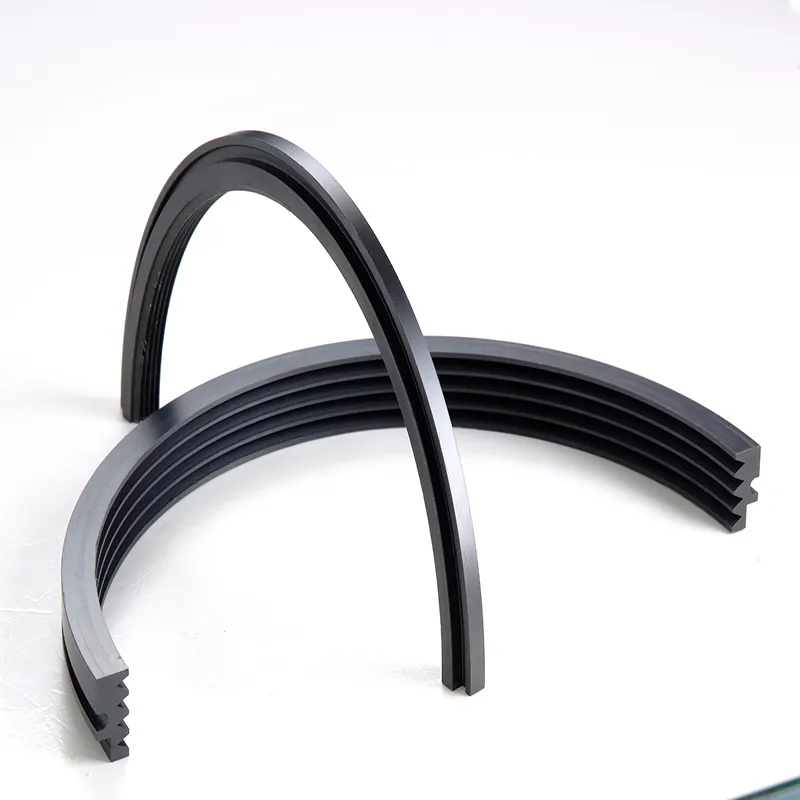
Performance and Technical Parameters
| Parameter | Specification | Basis / Notes |
|---|---|---|
Material grades |
PEEK-1000 (unfilled) · PEEK-GF30 (30 % glass fibre) · PEEK-CF30 (30 % carbon fibre) | Grade selected from temperature, PV and clearance-stability requirements |
Continuous operating temperature |
−60 °C to +260 °C | Limited by thermo-oxidative stability; not raised by fibre reinforcement |
Short-term peak temperature |
+300 °C, < 10 min, unloaded | Tm = 343 °C, Tg = 143 °C |
Pressure differential |
Standard designs ≤ 2 MPa; extended multi-tooth / stepped balance-drum designs to ≤ 8 MPa |
Non-contact throttling device. Value is per seal group, not per tooth; > 2 MPa requires FEA + CFD review |
Surface (peripheral) speed |
Stationary PEEK ring: ≤ 120 m/s rotor surface speed · Rotating PEEK ring: ≤ 100 m/s (CF30 ≤ 130 m/s) | Rotating-ring limit set by hoop stress σ ≈ ρv², de-rated for creep at temperature |
Equivalent rotational speed |
e.g. Ø50 mm → ≤ 45,000 rpm · Ø200 mm → ≤ 11,000 rpm · Ø600 mm → ≤ 3,800 rpm | rpm is a derived value — always specify diameter and speed together |
Radial clearance (cold, diametral/2) |
Ø30–80 mm: 0.08–0.15 mm · Ø80–200 mm: 0.12–0.25 mm · Ø200–400 mm: 0.20–0.40 mm · Ø400–600 mm: 0.30–0.60 mm | Plus differential thermal-growth allowance; scales with diameter, not with rpm alone |
Shaft diameter range |
Ø30 mm – Ø600 mm (larger by agreement) | Segmented construction above Ø400 mm |
Number of teeth |
2–15 (typ. 5–10) | Benefit saturates beyond ~10 teeth due to kinetic-energy carry-over |
Tooth profile |
Straight · inclined · stepped · honeycomb / hole-pattern | Stepped and honeycomb give the highest dissipation per axial length |
Tooth height |
1.5–6.0 mm | ≥ 8× radial clearance recommended |
Tooth pitch |
3–15 mm | Pitch/height ratio 1.5–3 for effective vortex dissipation |
Min. tooth root thickness |
≥ 0.8 mm (unfilled) · ≥ 1.0 mm (GF30/CF30) | Fibre-reinforced grades are notch-sensitive |
Surface roughness |
Tooth tip & flank: Ra 0.4–0.8 μm · Stator land: Ra 0.8–1.6 μm or honeycomb | Sharp, smooth tips maximise throttling; deliberate land texture adds damping |
Dimensional tolerance |
OD ±0.05 mm · ID ±0.03 mm · tooth profile ±0.02 mm | Measured at 23 °C / 50 % RH per ISO 291 |
Tensile modulus |
3.6–4.0 GPa (unfilled) · ~10 GPa (GF30) · ~24 GPa (CF30) | ISO 527-2 |
Thermal expansion (CTE) |
45–55 ppm/K (unfilled) · 20–25 (GF30) · 15–20 (CF30) | ISO 11359-2, below Tg. Critical clearance-design input |
Coefficient of friction |
0.34–0.40 (unfilled) · 0.15–0.25 (CF30) | vs. steel (dry). ASTM D3702 |
Water absorption |
0.10–0.15 % (24 h) · 0.45 % (saturation) | ISO 62; allow for dimensional change on large diameters |
Density |
1.32 (unfilled) · 1.40 (CF30) · 1.51 (GF30) g/cm³ | ISO 1183 |
Need Custom Specifications?
Contact our engineering team to discuss your specific requirements.
Submit Your Requirements
Application Fields
Centrifugal Compressors
Interstage, balance-drum and shaft-end seals in air, refrigeration and process-gas machines. A tighter, rub-tolerant clearance reduces recirculation and typically recovers 1–3 % stage efficiency versus a conservatively clearanced metallic labyrinth. Gas temperature at the seal ≤ 200 °C.
Turbomachinery — Low-Temp Sections
LP-end gland seals on steam turbines, turboexpanders, ORC turbines and cryogenic expanders. PEEK is applied where the local metal and fluid temperature stays within its 260 °C continuous limit; hot-section and supercritical steam duties (> 300 °C) require metallic, ceramic or abradable-metal seals.
Aerospace — Cold Sections
Fan and front LP-compressor stages, accessory gearboxes, APUs, fuel and lube pumps, and environmental-control-system shafting. At 1.32 g/cm³ a PEEK element is roughly 70 % lighter than titanium, contributing directly to thrust-to-weight. Not applicable to turbine-section or combustor-adjacent hardware.
Multistage High-Pressure Pumps
Interstage bushings, wear rings and throat bushings in boiler feedwater pumps, high-pressure injection pumps and SWRO desalination pumps. PEEK’s hydrolysis resistance suits hot water to ~180 °C (and short-term steam to 250 °C), while its non-galling behaviour tolerates transient contact typical of pump start-up.
Semiconductor Vacuum Equipment
In dry vacuum pumps, coaters and etchers, PEEK labyrinths provide shaft-to-bearing-chamber isolation and anti-backstreaming gas barriers. Vacuum-baked grades meet low-outgassing requirements; PEEK resists HF, Cl₂ and BCl₃ in the gas phase, though direct plasma exposure should be avoided.
Oil and Gas
Wellhead equipment, gas-lift and natural-gas compressors, LNG pumps. PEEK grades qualified to ISO 23936-2 / NORSOK M-710 withstand sour service (H₂S), rapid gas decompression and sand-laden erosion.
Tell Us About Your Application
Whether you are designing a high-speed centrifugal compressor or engineering a cryogenic expander, our team is here to help. Share your operating conditions, and our engineers will evaluate the optimal PEEK grade, clearance dimensions, and tooth profiles for your specific machinery.
- Material Grade Selection (PEEK-1000, GF30, CF30)
- Custom Radial Clearance & Differential Thermal-Growth Calculation
- FEA & CFD Review Support for High-Pressure Designs (> 2 MPa)
Ready to Discuss Your Project?
Click below to provide your specifications and connect with our engineering team.
Submit Your Requirements
Common Failure Causes and Remedies
Clearance opening / rising leakage
Causes
- Differential thermal expansion between the PEEK ring and steel shaft (the dominant cause).
- Under-specified initial clearance.
- Cumulative tooth-tip wear.
Remedies
- Recalculate clearance from the actual thermal map, not ambient dimensions.
- Specify PEEK-CF30 or a steel-carrier/PEEK-liner construction.
- Increase tooth count or switch to a stepped profile to recover throttling.
- Refine start-up and coast-down ramps.
Tooth fracture or chipping
Causes
- Rotor vibration or misalignment driving hard tooth-to-rotor contact.
- Tooth root below minimum thickness.
- Notch sensitivity in fibre-reinforced grades.
Remedies
- Verify rotor balance (ISO 21940) and alignment.
- Hold tooth root ≥ 0.8 mm (unfilled) / ≥ 1.0 mm (GF30, CF30).
- Add a generous root radius to suppress stress concentration.
- Consider unfilled PEEK where impact toughness outweighs stiffness.
Creep or thermal distortion
Causes
- Sustained compressive load above Tg (143 °C).
- Circumferential temperature gradient.
- Unsupported thin sections.
Remedies
- Select GF30 or CF30 for elevated-temperature load-bearing sections.
- Provide full radial support in a metallic carrier.
- Add cooling or a thermal barrier to hold the seal below 200 °C.
Chemical attack or swelling
Causes
- Exposure to concentrated sulphuric or fuming nitric acid, or halogenated sulphonic acids.
- Prolonged immersion in a small number of aggressive solvents.
Remedies
- Confirm media compatibility before selection.
- Switch to PTFE-based or metallic construction for strong oxidising acids.
- Apply a barrier fluid or buffer gas.
- Inspect for surface crazing at each shutdown.
Rub-induced local melting
Causes
- Sustained heavy contact at high surface speed.
- Frictional heating drives the contact zone above 343 °C.
Remedies
- Verify that the clearance covers the full transient excursion envelope.
- Specify CF30 for its lower friction and higher thermal conductivity.
- Ensure adequate buffer-gas or process flow across the seal.
Installation-induced failure
Causes
- Eccentric assembly.
- Tooth damage during handling.
- Incorrect axial location.
Remedies
- Use a dedicated pilot fixture (concentricity ≤ 0.05 mm TIR).
- Protect tooth tips in transit and assembly.
- Verify axial position and running clearance with feeler gauge or dial indicator before trial run.
Facing a Technical Challenge?
Tell us about the difficulties you are currently encountering. Our engineering team is ready to analyze your application and provide a tailored solution.Submit Your Application Details
Our engineers will respond to you within 24 hours.Essential Parameters for Procurement and Selection
Provide the following when requesting a quotation to ensure an accurate engineering assessment:
FAQ — Frequently Asked Questions
Q1: Can a PEEK labyrinth seal eliminate leakage entirely?
No. A labyrinth is a non-contact throttling device and cannot achieve zero leakage by definition. It controls leakage to a designed allowable value through clearance, tooth count and profile optimisation. Because PEEK tolerates rubbing, it can be built to a tighter clearance than a metallic seal of the same duty, which is the source of the leakage reduction. Where a true zero-leakage boundary is required, combine the labyrinth with a mechanical seal, dry-gas seal or buffer-gas system.
Q2: Why can a PEEK labyrinth run at a smaller clearance than a metal one?
Two reasons, and neither is thermal expansion. First, PEEK’s tensile modulus (3.6–4.0 GPa) is roughly two orders of magnitude below steel, so contact loads are absorbed elastically instead of being transmitted into the rotor. Second, PEEK abrades sacrificially against a hardened shaft without galling, scoring or sparking, so a transient rub is a benign event rather than a machine-damaging one. This allows the cold assembly clearance to be reduced. Note that PEEK’s CTE is higher than steel’s, so the hot running clearance must be explicitly compensated — through CF30 grade selection or a metallic carrier.
Q3: How do I choose between PEEK-1000, PEEK-GF30 and PEEK-CF30?
PEEK-1000 (unfilled) offers the highest toughness and the broadest chemical resistance, and is preferred where impact and notch sensitivity matter. PEEK-GF30 raises stiffness and creep resistance and is electrically insulating, suiting loaded sections at elevated temperature. PEEK-CF30 provides the highest stiffness, the lowest friction, the best wear resistance, and — critically for labyrinths — a CTE of 15–20 ppm/K that closely tracks steel, giving the most stable running clearance across the temperature range. All three share the same 260 °C continuous ceiling.
Q4: What is the true maximum operating temperature?
260 °C continuous, with short-term excursions to 300 °C. This ceiling is set by thermo-oxidative degradation of the polymer backbone and is not increased by glass or carbon fibre reinforcement — reinforcement raises the heat-deflection temperature and load-bearing capability, not the chemical service limit. Above 300 °C, PEEK is not a candidate; specify metallic, abradable-metal or ceramic labyrinth seals.
Q5: How is the clearance determined?
Start from a diameter-proportional baseline (see the parameter table), then add the calculated differential thermal growth between the PEEK ring and the shaft over the full operating envelope, the manufacturing and installation tolerance stack, and the expected rotor vibration amplitude plus transient excursion. Finally, verify that the resulting leakage meets the specification via a CFD or bulk-flow calculation. Speed alone is not a sufficient input — an 0.10 mm clearance is routine at Ø50 mm and unachievable at Ø500 mm.
Q6: What should be observed during installation?
Ensure the bore and seal are clean and burr-free; use a pilot fixture to hold concentricity within 0.05 mm TIR; protect the tooth tips throughout handling; hold the axial location strictly to drawing; verify running clearance by feeler gauge or dial indicator before closing the machine; and run a no-load trial while monitoring vibration and acoustic signature.
Q7: How should the seal be maintained?
At each shutdown, inspect the tooth tips for crazing, chipping and wear; measure the radial clearance and replace once it exceeds 150 % of the design value; trend the system leakage rate and investigate any step change; remove deposits from the throttling chambers, since fouling collapses the expansion volumes that produce the pressure drop; and log running hours against temperature and pressure to calibrate the replacement interval.
Q8: What service life should be expected?
Under moderate duty — seal temperature ≤ 200 °C, surface speed ≤ 60 m/s, vibration within API limits — 20,000 to 30,000 operating hours (roughly 3–4 years of continuous service) is typical. Severe duty involving high temperature, high surface speed, frequent start-stop cycling or particulate-laden media may reduce this to 8,000–15,000 hours. Condition-based inspection is more reliable than a fixed calendar interval.
Ready to Optimize Your Engineering Performance?
Partner with our specialists to get tailored material recommendations, precise clearance calculations, and fast quoting for your specific application.
Submit Your Requirements
Our engineering team will review your parameters and respond within 24 hours.