
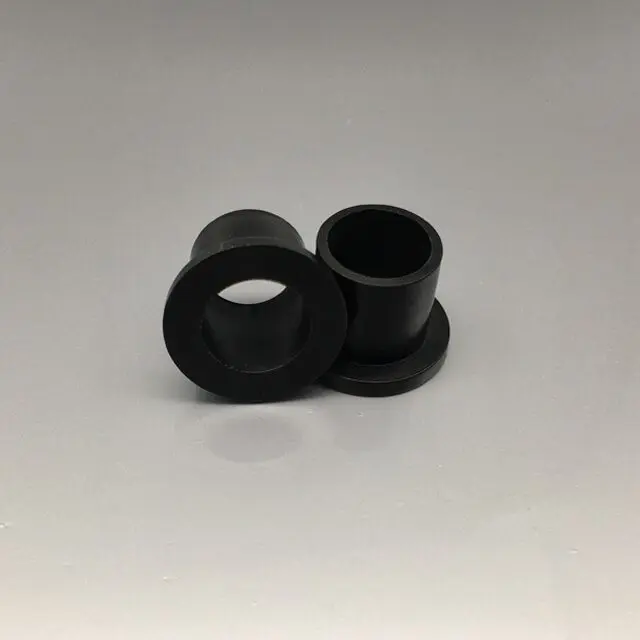
PEEK Flange Bearing | Self-Lubricating Bushing

A PEEK flange bearing is a self-lubricating plain bearing with an integral flange at one end. The cylindrical body carries radial load and guides the shaft, while the flange provides axial location and carries thrust load, eliminating the separate thrust washer, snap ring or shoulder that a plain sleeve bushing requires.

  • Manufacturing Process: CNC machining or compression molding from extruded stock

  • Material Grades: Unfilled PEEK, GF30, CF30, or CF/PTFE tribological blend

  • Bore Surface Roughness: Ra ≤ 0.8 µm

  • Flange Face Flatness: ≤ 0.03 mm

  • Dimensional Tolerance: ± 0.05 mm

  • Operating Temperature Range: −60 °C to +260 °C

  • Lubrication Modes: Dry-running, water-lubricated, or grease-lubricated

  • Maintenance Requirement: Zero lubrication schedule needed

  • Chemical Resistance: Resistant to a wide range of process chemistry

  • Service Life: 2 to 4 times longer than traditional bronze flange bushings (in dry or minimally lubricated applications)

Contact Us

Engineering Guidelines

Two Design Rules That Govern Every PEEK Bushing Installation

Critical tolerances and thermal considerations for perfect running clearances.


Rule 01

Interference Transfer & Bore Closure

The bore closes when you press the bushing in. For a thin-wall bushing pressed into a rigid housing, roughly 70–90% of the diametral interference transfers to the bore.

Example: A Ø26 mm OD bushing fitted with 0.04 mm interference loses about 0.028–0.036 mm of bore.

Solution: Either pre-oversize the bore by this amount, or ream/bore to finished size after fitting. The latter is Allstar’s recommended practice for ≤ 0.05 mm running clearance.
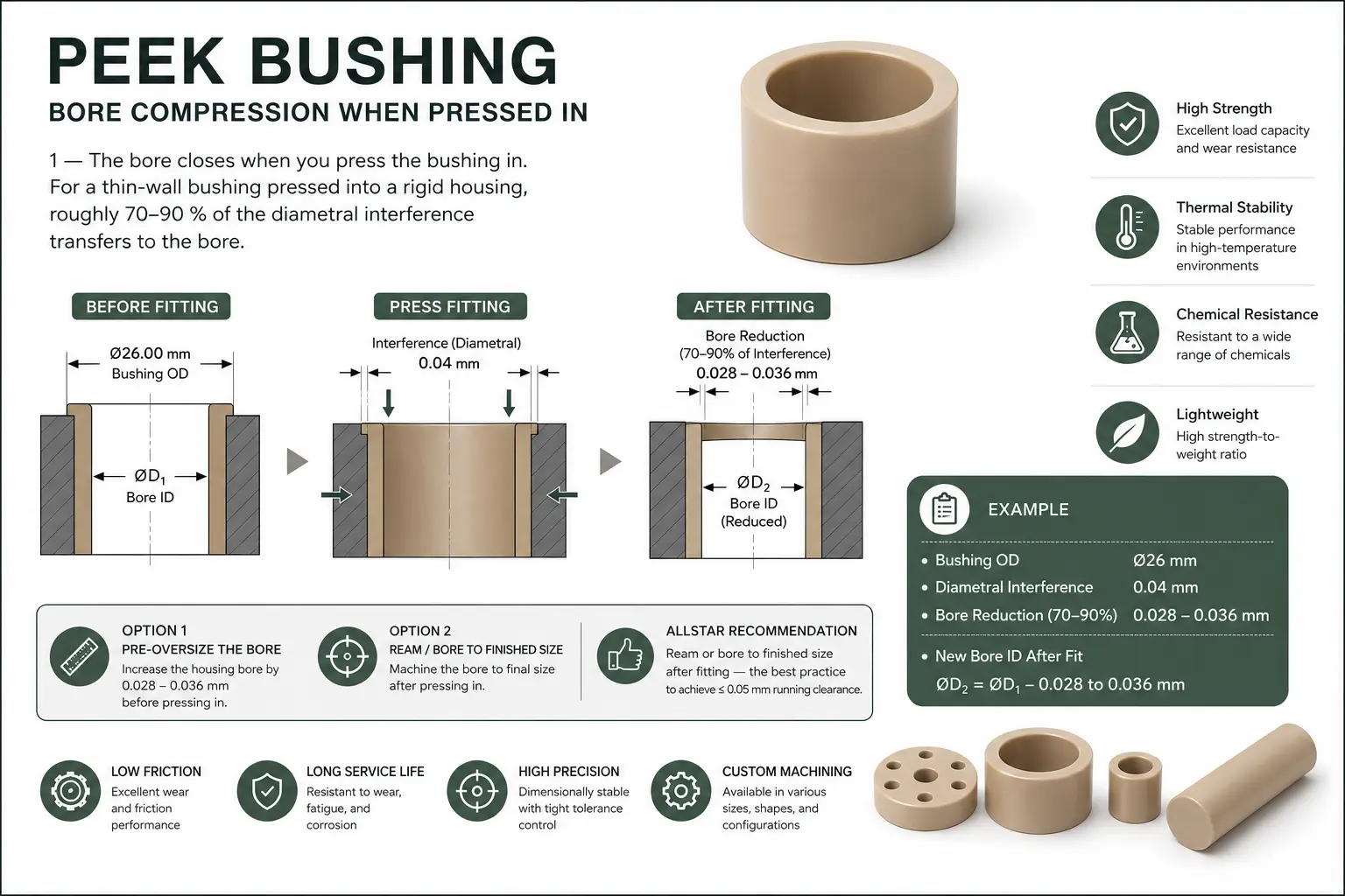
PEEK Bushing Interference Fit

Rule 02

Thermal Expansion Constraints

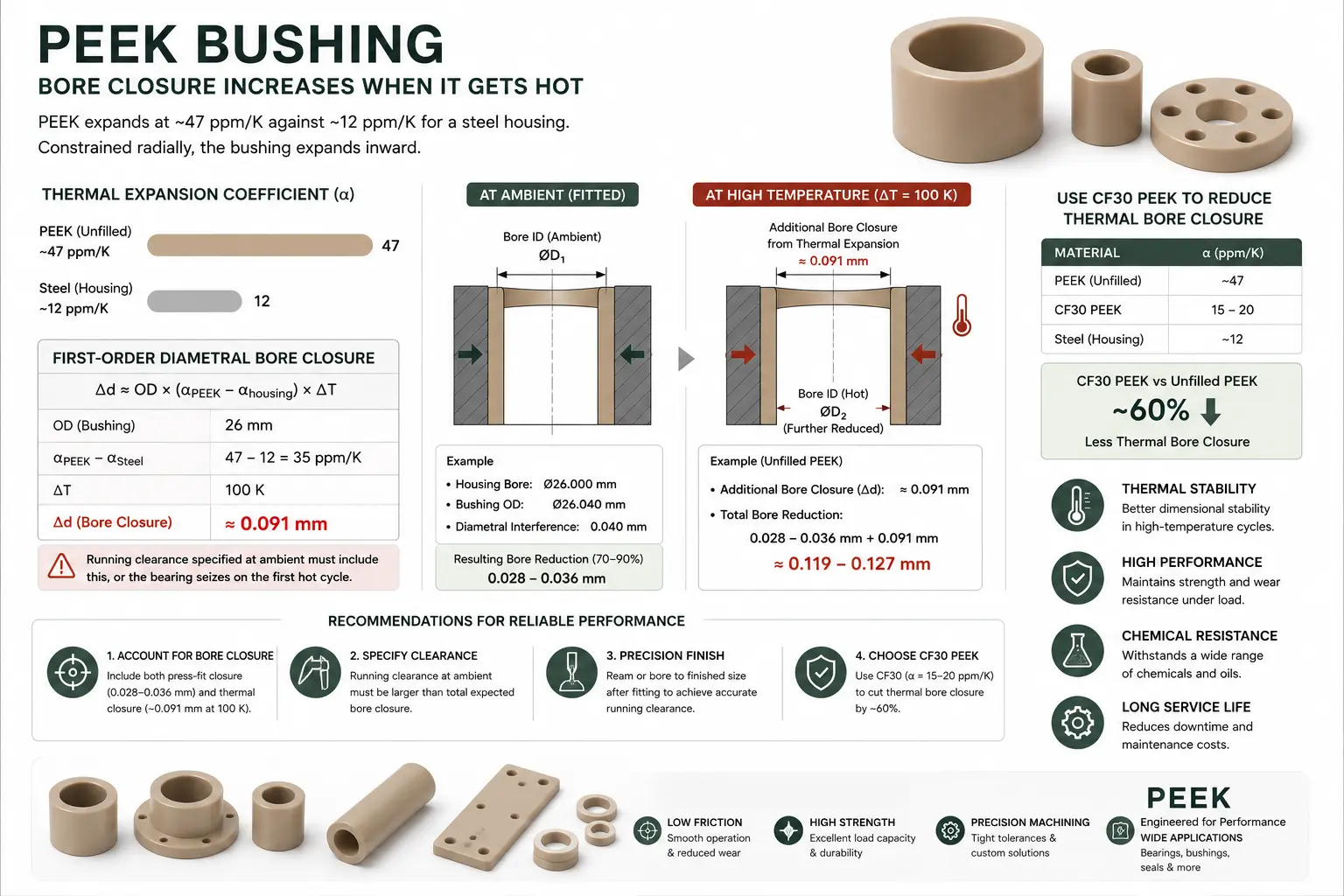
The bore closes further when it gets hot. PEEK expands at ~47 ppm/K against ~12 ppm/K for a steel housing. Constrained radially, the bushing expands inward.

First-order diametral closure:
Δd ≈ OD × (αPEEK − αhousing) × ΔT

Calculation: For OD 26 mm and ΔT = 100 K:
26 × 35 × 10−6 × 100 ≈ 0.091 mm of bore closure.

Running clearance specified at ambient must include this, or the bearing seizes on the first hot cycle. Pro Tip: Specify CF30 (α = 15–20 ppm/K) to cut the effect by ~60%.


Thermal Expansion of PEEK vs Steel
 

Core Advantages

Engineered for extreme performance, our PEEK flange bearings deliver superior reliability across demanding applications.

Feature Specification & Benefit
Maintenance-free operation Dry-running capability removes the lubrication schedule, the grease line and the risk of lubricant contaminating product.
Thermal capability −60 °C to +260 °C continuous, +280 °C short-term (< 10 min, unloaded). Tm 343 °C, Tg 143 °C.
Integral axial location The flange replaces a thrust washer plus retaining ring, cutting part count and assembly time.
Chemical resistance Dilute acids and caustics, hydrocarbons, hot water and steam, most solvents.
Not for concentrated sulphuric acid, oleum, fuming nitric or chlorosulphonic acid.
Hydrolysis resistance Retains > 95% of properties after prolonged immersion in hot water and steam; suitable for submerged and washdown service.
Non-galling, shaft-friendly Will not seize or weld to a steel shaft, and cannot scuff a soft shaft the way a bronze bushing can under boundary lubrication.
Electrically insulating Breaks stray-current and galvanic paths.
Clean and compliant FDA 21 CFR 177.2415, EU 10/2011 and USP Class VI grades available; no lubricant migration.

Need Application-Specific Advice?

Our engineering team can help you determine the exact running clearances and thermal tolerances for your specific operating environment.

Direct Contact: Richard

Technical Sales & Application Engineer

Performance and Technical Parameters

Basis of data: Values are for machined parts from extruded stock shapes, tested at 23 °C / 50% RH per ISO 291 unless stated. Injection-moulded PEEK exhibits higher strength and modulus due to fibre orientation; where injection-moulded properties are required, request the moulded-grade datasheet.

Tribological Limits

Condition Continuous PV limit (MPa·m/s) Notes
Unfilled PEEK, dry 0.08 – 0.15 Toughest grade, lowest PV
CF30, dry 0.20 – 0.35 Higher thermal conductivity aids heat removal
Tribological blend (CF + PTFE + graphite), dry 0.30 – 0.50 Recommended for all dry-running duty
Water-lubricated 0.50 – 0.80 Water film plus convective cooling
Grease / oil-lubricated (mixed film) 1.2 – 2.0 Requires maintained lubricant supply

Temperature derating (multiply the PV limit):
23–80 °C × 1.0 · 100 °C × 0.75 · 150 °C × 0.50 · 200 °C × 0.30 · 230–260 °C × 0.20.

PV Calculation: PV is calculated as P × V, where P = radial load / projected area (d × L) in MPa and V = π·d·n / 60,000 in m/s (d in mm, n in rpm).

Load and Speed

Parameter Specification Notes
Permissible static surface pressure (v ≈ 0, 23 °C) ≤ 100 MPa (unfilled)
≤ 120 MPa (GF30 / CF30)
Derived from 1% compressive yield with safety factor; derate to ~40 MPa at 200 °C
Permissible dynamic surface pressure Governed by the PV limit above, not by an independent pressure figure A single dynamic MPa value without a stated velocity is meaningless
Maximum sliding velocity ≤ 2.0 m/s (dry, minimal load)
≤ 4.0 m/s (lubricated)
At these speeds only very low pressure is permissible — PV governs
Motion types Continuous rotation, oscillation, linear reciprocation Oscillating duty permits ~1.5× the rotating PV

Geometry and Tolerance

Parameter Specification Notes
Size range Bore Ø6–80 mm · OD Ø10–100 mm · body length 6–80 mm · flange OD Ø12–120 mm · flange thickness 1.5–8 mm Inch equivalents ⅛”–3″ available
OD (press-fit) Supplied with a specified diametral interference of 0.02–0.05 mm relative to the nominal housing bore — equivalent to an r6 / s6 band. Not h6/h8, which cannot generate interference against an H7 housing. Interference scaled to OD; consult for OD > 60 mm
Bore Two options: (a) finish-machined bore, pre-oversized by 0.7–0.9 × the interference; (b) rough bore with 0.3–0.5 mm stock, reamed to size after fitting. Option (b) is preferred where running clearance < 0.05 mm and gives the tightest achievable clearance
Recommended running clearance (installed, at temperature) Ø6–12: 0.03–0.06 mm
Ø12–25: 0.05–0.09 mm
Ø25–50: 0.08–0.14 mm
Ø50–80: 0.12–0.20 mm
Plus the thermal-closure allowance from the formula above
Bore roughness Ra ≤ 0.8 µm (working) · Ra ≤ 1.6 µm (non-working) ISO 4287
Flange face Flatness ≤ 0.03 mm · Ra ≤ 1.6 µm ISO 1101
Roundness Bore ≤ 0.03 mm · OD ≤ 0.05 mm
Length / flange thickness tolerance ± 0.10 mm
Housing bore requirement H7 (H8 acceptable for clearance-fit designs), Ra ≤ 1.6 µm, concentricity ≤ 0.08 mm
Flange seat requirement Flatness ≤ 0.03 mm, depth tolerance ± 0.05 mm, support area ≥ 80% of flange area

Material Properties (machined from extruded stock)

Property Unfilled PEEK GF30 CF30 CF/PTFE blend Standard
Density (g/cm3) 1.32 1.51 1.40 1.44 ISO 1183
Tensile strength (MPa) ≥ 95 ≥ 105 ≥ 120 ≥ 90 ISO 527-2
Tensile modulus (GPa) 3.6 ~7.0 ~13 ~8 ISO 527-2
Flexural strength (MPa) ≥ 160 ≥ 180 ≥ 200 ≥ 150 ISO 178
Compressive strength, 1% yield (MPa) ≥ 125 ≥ 140 ≥ 145 ≥ 110 ISO 604
Hardness Rockwell M99 / R126
(≈ Shore D 87–90)
M100+ M102+ M95 ISO 2039-2
CTE, < Tg (×10-6/K) 45–50 20–25 15–20 25–30 ISO 11359-2
Friction coefficient vs. steel, dry 0.34–0.40 0.36–0.42 0.20–0.25 0.15–0.20 ASTM D3702
Friction coefficient, lubricated 0.10–0.15 0.12–0.16 0.08–0.12 0.05–0.10 ASTM D3702
Specific wear rate (mm3/N·m) ~1×10⁻⁵ dry ~2×10⁻⁵ dry ~3×10⁻⁶ dry ~8×10⁻⁷ dry ASTM G137
Compressive creep, 24 h @ 200 °C / 10 MPa ≤ 3% ≤ 1.5% ≤ 1.2% ≤ 3% ISO 899-2
Water absorption, 24 h / saturation (%) 0.10–0.15 / 0.45 0.08 / 0.35 0.08 / 0.35 0.10 / 0.40 ISO 62
Thermal conductivity (W/m·K) 0.25 0.43 0.90 0.60 ISO 22007

💡 Grade Selection Shortcut

  • Dry running: → CF/PTFE blend
  • Hot and heavily loaded: → GF30 or CF30
  • Tight clearance at high ΔT: → CF30 (lowest CTE)
  • Impact or shock load on the flange: → unfilled

Recommended Shaft and Housing

Item Requirement
Shaft hardness ≥ HRC 45 minimum, ≥ HRC 50 recommended; hardened & ground, nitrided, hard-chromed or ceramic-coated
Shaft roughness Ra 0.2–0.6 µm — a too-smooth shaft (Ra < 0.1 µm) starves the transfer film and can raise dry friction
Shaft straightness / roundness ≤ 0.02 mm / 100 mm · ≤ 0.02 mm
Shaft material to avoid Soft stainless (annealed 304/316, < HRC 25) in dry running — prone to scuffing
Housing bore H7 (H8 for clearance designs), Ra ≤ 1.6 µm
Housing material CTE Report it — it drives the thermal-closure calculation. Aluminium housings (α ≈ 23 ppm/K) reduce closure by ~30% versus steel

Application Fields

Proven performance across diverse and demanding industrial environments.

Printing and Packaging

Printing & Packaging

Paper-guide rollers, folder and slitter mechanisms, ink-train idlers. Typical duty 200–1,500 rpm on Ø10–30 mm shafts (v ≈ 0.1–1.2 m/s) with light radial load, running dry or with occasional grease. The flange takes web-tension thrust and side registration loads. Dry running eliminates any risk of oil marking the substrate.

Textile Industry

Textile

Yarn-guide and tension-wheel bushings, heald-frame and dobby linkage pivots, winder traverse mechanisms — i.e. guide, oscillating and moderate-speed rotating positions (v ≤ 2 m/s). High-speed spindles above roughly 10,000 rpm are rolling-element applications and outside the PEEK plain-bearing envelope. PEEK resists fibre dust abrasion and needs no lubrication that could soil yarn.

Food and Beverage Processing

Food & Beverage

Mixer and agitator shaft bushings, conveyor roller ends, filler and slicer linkages. Compliant to FDA 21 CFR 177.2415 and EU 10/2011; withstands CIP (80 °C caustic), acid CIP and SIP (121–134 °C saturated steam). Hydrolysis resistance is the decisive property here — most engineering thermoplastics fail in repeated steam cycling.

Automation and Robotics

Automation & Robotics

End-effector pivots, linear-module guide bushings, pneumatic slide bearings, gripper linkages. The flange sets axial datum and carries push-pull load. Where the bushing rotates with the moving member, the 1.32 g/cm³ density reduces reflected inertia; in fixed-housing positions the benefit is assembly mass, not inertia.

Office and Imaging Equipment

Office & Imaging

Paper-feed and registration roller bearings in copiers, printers and scanners. Dry running prevents grease migration onto media, and the polymer pair avoids the stick-slip squeal characteristic of metal bushings at low speed.

Fitness Equipment

Fitness Equipment

Treadmill deck and roller bearings, flywheel and crank pivots, cable-machine guide bushings. Tolerates frequent start-stop and shock loading (specify unfilled grade for impact), and resists perspiration (pH 4.5–7) which pits aluminium and corrodes plated steel.

Appliances and Wet Environments

Appliances & Wet Env.

Washer agitator and drum bushings, pump and blower shaft supports, dishwasher spray-arm pivots. Stable in 60–90 °C detergent solutions with < 0.3% dimensional change. The flange–seat interface forms a dust and splash labyrinth that contributes to the assembly’s overall ingress protection.

Submerged and Marine Service

Submerged & Marine

Water and wastewater pump bushings, sludge-scraper and gate pivots, steering and winch linkages, ROV joint bearings. Hydrostatic pressure is not a limiting factor for PEEK. Seawater, chlorinated and ozonated water are all within the envelope; GF30 is preferred for long-term seawater immersion.

Not sure which PEEK grade fits your specific application?

Tell us about your operating environment (speed, load, temperature, chemicals), and our engineering team will recommend the optimal material and machining tolerances.

Direct Contact: Richard (Technical Sales & Application Engineer)

Common Failure Causes and Remedies

1

Seizure or binding shortly after installation

Failure Illustration 1

CAUSES

  • Bore closure from press-fit interference not accounted for (the single most common cause)
  • Thermal bore closure on first hot cycle
  • Housing bore undersize
  • Flange not seated, cocking the bushing

REMEDIES

  • Apply the bore-closure rules in the H1 panel — pre-oversize the bore by 0.7–0.9 × interference, or ream after fitting
  • Add the thermal-closure allowance for the full ΔT
  • Verify housing bore to H7 before fitting
  • Confirm ≥ 80 % flange-seat contact with a feeler gauge

2

Flange cracking at the root

Failure Illustration 2

CAUSES

  • Press force applied through the flange instead of the body
  • Installation step not supporting the flange (overhang)
  • Flange thinner than 1.5 mm
  • Sharp root with no transition radius
  • Thermal shock
  • Notch sensitivity in GF30/CF30

REMEDIES

  • Press on the body face only, never on the flange, with a stepped pilot tool
  • Support ≥ 80 % of the flange area
  • Hold flange thickness ≥ 2.5 mm for meaningful thrust load
  • Specify root radius R1.0–2.0 mm (reduces peak root stress by 50–70 %)
  • Limit heating/cooling rate to ≤ 50 °C/h
  • Specify unfilled PEEK where impact governs

3

Bore wear, scoring or transfer-film breakdown

Failure Illustration 3

CAUSES

  • PV limit exceeded (recalculate with the temperature derating)
  • Shaft too soft (< HRC 45) or too rough (> Ra 1.0 µm)
  • Shaft too smooth (< Ra 0.1 µm) preventing film formation
  • Abrasive ingress
  • Repeated dry starts under load

REMEDIES

  • Recompute PV including derating and reduce load, speed or increase L/d
  • Upgrade shaft to ≥ HRC 50 with Ra 0.2–0.6 µm
  • Fit filtration to ≤ 25 µm
  • Pre-lubricate and run in at 30 % speed / 50 % load for 30–60 min
  • Step up to the CF/PTFE tribological blend (specific wear rate ~10× lower)

4

Flange face wear, indentation or creep

Failure Illustration 4

CAUSES

  • Axial load exceeding the flange’s projected-area capability
  • Poor seat flatness (> 0.05 mm) concentrating load on an edge
  • Sustained load above Tg (143 °C)
  • Axial shock

REMEDIES

  • Compute thrust stress as $F / [\frac{\pi}{4} \times (D_{\text{flange}}^2 – D_{\text{bore}}^2)]$ and hold it inside the derated static limit
  • Machine the seat to ≤ 0.03 mm flatness for full contact
  • Specify GF30 or CF30 above 120 °C (creep 1.2–1.5 % vs 3 %)
  • Add a hardened thrust washer where shock is present
  • Increase flange OD before increasing thickness — capability scales with area

5

Loss of press-fit retention / bushing spinning

Failure Illustration 5

CAUSES

  • Insufficient interference
  • Housing bore oversize or too rough (> Ra 3.2 µm)
  • Thermal interference loss where the housing is aluminium and expands faster than expected
  • Creep relaxation of the interference under sustained radial load
  • Fretting under vibration

REMEDIES

  • Verify residual interference ≥ 0.01 mm at maximum operating temperature — note that with a steel housing PEEK gains interference when hot, but with an aluminium housing (α 23 ppm/K) the margin shrinks and must be checked
  • Machine housing to H7 / Ra ≤ 1.6 µm
  • Add retained-strength adhesive (anaerobic retaining compound) where vibration is present
  • Add an anti-rotation flat, pin or key for high-torque duty

6

Abnormal noise

Failure Illustration 6

DIAGNOSTIC SEQUENCE (CAUSES)

  • Knocking with shaft shake ⇒ clearance beyond 0.20 mm, replace
  • Squeal at low speed ⇒ clearance too tight or transfer film not formed, re-check clearance and run-in
  • Gritty grinding ⇒ abrasive ingress, clean and filter
  • Periodic tick synchronised to shaft rotation ⇒ shaft defect or runout > 0.10 mm
  • Intermittent click ⇒ press-fit loss
  • Broadband buzz ⇒ structural resonance, not the bearing

GENERAL NOTES

  • New-install noise is almost always clearance or seating
  • Noise appearing after service is wear or lubrication loss
  • Noise following a thermal excursion is bore closure or distortion

Essential Parameters for Procurement and Selection

  • Bearing dimensions — bore × OD × body length × flange OD × flange thickness (e.g. Ø20 × Ø26 × 30 × Ø35 × 3 mm), or the envelope available
  • Housing material and its bore tolerance — required for the interference and thermal-closure calculation
  • Shaft material, surface hardness (min. HRC 45, recommended ≥ HRC 50), roughness and diameter tolerance
  • Radial load (N) and axial load (N) — separately, with duty cycle
  • Speed (rpm) or oscillation frequency and swept angle, plus motion type
  • Temperature at the bearing — steady-state range and transient peaks (not ambient)
  • Lubrication regime — dry, water, grease, oil, or process medium
  • Medium and environment — chemistry, particulate content, washdown chemistry
  • Target service life (hours or cycles) and acceptable wear budget
  • Certification requirements — FDA / EU 10/2011 / USP Class VI / RoHS / REACH / ATEX

Allstar returns within 24 hours: A computed PV and thrust-stress check against the derated limits, a grade recommendation, the interference and finished-bore specification (including the thermal-closure allowance for your housing material), a 2D drawing and STEP file, and where required a sample-qualification protocol covering wear, thermal cycling and dimensional stability.

Ready to Discuss Your Design?

Send your 2D drawings (PDF) or 3D CAD files (STEP/IGES) directly to Richard and our engineering team. We will review your tolerances and provide a comprehensive manufacturing assessment.

Email:T1@peekrources.com


FAQ

Q1: PEEK flange bearing vs. bronze flange bushing — what actually changes?

Lubrication is the main one: PEEK runs dry or water-lubricated, so the grease line, the schedule and the contamination risk all disappear, whereas a bronze bushing under boundary lubrication will scuff and eventually seize. PEEK is chemically inert across a far wider pH range and does not dezincify or pit in chloride service. It is electrically insulating, breaking stray-current paths. At 1.32 g/cm³ it is roughly 15% of bronze density. It will not gall or weld to a steel shaft.

On the other side of the ledger, bronze carries higher static load, conducts heat far better, and holds tighter clearance across temperature — PEEK’s 47 ppm/K expansion is the design constraint you must engineer around. On food-contact duty, traditional leaded bronzes (e.g. C93200) are restricted, though lead-free bronzes such as C89833 and RG5 are available and hold NSF/ANSI 61 & 372 certification — the PEEK advantage there is compliance combined with dry running, not compliance alone.

Q2: Flanged vs. plain sleeve — when is the flange worth it?

The flange earns its cost when there is genuine axial load or an axial datum requirement. It replaces a thrust washer plus retaining ring or machined shoulder, typically removing two parts and shortening assembly. It gives a repeatable axial reference at the bearing itself rather than at a downstream feature. It adds 20–40% heat-dissipation area, worth 5–15 °C of running temperature in dry duty. And the flange-to-seat interface forms a dust labyrinth.

Against that, material use rises 10–15%, an extra machining operation is required, and the flange root becomes a stress-concentration site that needs a proper radius. Where the load is purely radial and axial location already exists, a plain sleeve is the cheaper answer.

Q3: How are flange dimensions determined?

Flange OD is typically 1.4–1.8 × body OD — a Ø26 mm body pairs with a Ø36–47 mm flange. Thrust capability scales with the annular area π/4 × (Dflange² − Dbore²), so widening the flange buys capability far more efficiently than thickening it.

Flange thickness follows from a bending check on that annulus against the allowable stress (unfilled PEEK ~40 MPa, GF30 ~60 MPa at ambient, both derated for temperature), landing at 1.5–3 mm for light thrust, 3–5 mm medium, 5–8 mm heavy. Always specify a root radius R1.0–2.0 mm at the flange-to-body junction and a C0.3–0.5 mm outer chamfer. For thrust loads above roughly 60% of the derated allowable, or for any cyclic thrust, verify by FEA and keep peak root stress below 70% of allowable.

Q4: What service life should be expected?

Life is set by the wear budget divided by the wear rate, and the wear rate is a function of PV, temperature and cleanliness. Indicative figures at the stated PV, ambient temperature and a clean HRC 50 shaft:

Regime Wear rate Bore wear limit Indicative life
Oil/grease lubricated, PV ≈ 1.0 ~0.003 mm/1000 h 0.20 mm 30,000–50,000 h
Water lubricated, PV ≈ 0.6 ~0.008 mm/1000 h 0.20 mm 15,000–25,000 h
Dry, tribo blend, PV ≈ 0.3 ~0.015 mm/1000 h 0.20 mm 8,000–15,000 h
Dry, unfilled, PV ≈ 0.10 ~0.020 mm/1000 h 0.20 mm 6,000–10,000 h
Contaminated (dust/abrasive) ~0.025–0.05 mm/1000 h 0.20 mm 3,000–8,000 h

Flange axial wear typically runs at ⅕–⅓ of the radial rate; replace at 20% of flange thickness. Other end-of-life indicators: clearance beyond 2× the installed value, axial float > 0.5 mm, a step change in running temperature (> 20 K rise), onset of noise, or visible discolouration and embrittlement. Raise life most reliably by stepping up to the CF/PTFE blend, upgrading shaft hardness to HRC 55–60, filtering the environment, and lowering PV via a longer bearing (increase L, not just d).

Q5: Which grade should I choose?
  • Unfilled: For impact and shock, frequent start-stop, best chemical breadth and the toughest flange — but the lowest PV and highest CTE.
  • GF30: For elevated temperature under load. ~2× the stiffness, half the creep, CTE cut to 20–25 ppm/K; slightly higher friction and notch-sensitive.
  • CF30: Where clearance must hold at high ΔT. CTE 15–20 ppm/K closely tracks steel, thermal conductivity ~4× higher (which directly raises the usable PV), wear resistance ~3× better; most brittle of the three, so avoid on impact-loaded flanges.
  • CF/PTFE tribological blend: For all dry-running duty. Lowest friction (0.15–0.20 dry) and lowest wear rate by roughly an order of magnitude; mechanical strength is the trade-off.

In practice: dry running → blend; hot and loaded → GF30; tight-clearance hot → CF30; shock → unfilled.

Q6: How should the bearing be installed?

Clean and deburr the housing bore and shaft; verify bore to H7 and the flange seat to ≤ 0.03 mm flatness. Press on the body face only — never through the flange — using a stepped pilot that centres in the bore, at ≤ 3 mm/s on a press, never by hammering. A light film of assembly lubricant on the OD reduces press force and scoring.

If interference exceeds 0.04 mm, warm the metal housing to 80–100 °C (do not exceed 120 °C) rather than chilling the bushing; cryogenic shrinking of PEEK is not recommended — at deep-cryogenic temperatures PEEK embrittles and the thin flange root can micro-crack. Confirm the flange is fully seated (gap < 0.05 mm, four-point variance ≤ 0.03 mm, contact ≥ 80 %). Then ream or bore to the finished size if that option was specified, and verify roundness ≤ 0.03 mm and concentricity ≤ 0.05 mm.

Bolt-fixed flanges: tighten diagonally in three stages to the specified torque (± 5%) with a thread-locking compound. Commission with a run-in at 30% speed and 50% load for 30–60 min, holding temperature rise below 50 K.

Q7: Can it run submerged or in washdown?

Yes — this is one of PEEK’s strongest positions. Water absorption is 0.10–0.15% at 24 h and 0.45% at saturation, with dimensional change under 0.3%, and PEEK resists hydrolysis in hot water and steam where most engineering thermoplastics degrade; after long-term immersion it retains over 95% of its properties.

Water acts as both lubricant and coolant, giving a PV limit of 0.5–0.8 MPa·m/s (reduce to ≤ 0.4 in silt-laden water). Hydrostatic pressure is not a limiting factor — PEEK is used routinely in deep-sea and downhole service, so ROV and subsea depth capability is set by the housing and clearance design, not by the polymer. Applications include water and wastewater pumps (≤ 80 °C), sludge scrapers and gates, chlorinated and ozonated systems, marine steering and winch linkages, and ROV joints. Specify GF30 for long-term seawater immersion, de-scale and de-foul on a 6-month interval, and for UPW service request the low-extractables grade with verified ionic (< 1 ppb) and particulate (< 0.1 ppb) release.

Q8: How do I calculate whether my application fits?

Four checks, in order:

  1. PV: compute P = Fradial / (d × L) and V = π·d·n / 60,000, multiply, then compare against the grade’s PV limit after applying the temperature derating factor.
  2. Thrust stress: Faxial / [π/4 × (Dflange² − Dbore²)] against the derated static limit.
  3. Bore closure: press-fit closure (0.7–0.9 × interference) plus thermal closure (OD × Δα × ΔT) must leave the required running clearance at maximum temperature.
  4. Retention: residual interference ≥ 0.01 mm at maximum temperature, accounting for the housing material’s own expansion.

If any check is marginal, the first lever is increasing L (lowers P and PV simultaneously), the second is grade selection, and the third is adding lubrication. Send the operating data and Allstar’s engineering team will run all four checks and return the calculation sheet.

Company Profile

About Dalian Allstar Material

Dalian Allstar Material designs and manufactures high-performance polymer bearings and sealing components in PEEK, PI and PTFE. In-house capability spans compound formulation, injection moulding, precision CNC turning and grinding, and full verification — CMM, roughness and roundness metrology, and pin-on-disc and journal-bearing tribology rigs for PV, friction and wear validation per ASTM D3702 and G137.

We supply flange bearings, sleeve bushings, thrust washers and wear rings to printing, textile, food-processing, automation, appliance and marine OEMs, and return a calculated technical proposal with drawing and STEP file within 24 hours.